
How to Create Good AWS Architecture Diagrams

Estimated Reading Time: 4 minutes
Last Updated: 2025-04-20
Disclaimer: The details described in this post are the results of my own research and investigations. While some effort has been expended in ensuring their accuracy - with ubiquitous references to source material - I cannot guarantee that accuracy. The views and opinions expressed on this blog are my own and do not necessarily reflect the views of any organization I am associated with, past or present.
Cloud Architectures
When it comes to software architecture diagrams, the iceberg is surprisingly deep.
On the surface, conceptual designs are highly abstracted and accessible, but keep diving down and the complexity of the physical architecture becomes more transparent.
As a data engineer working with AWS, I usually focus on creating logical cloud service architectures - I design how AWS components work in concert to shuttle data from A to B. This has meant that my diagrams need to be well-organised and very clear so that other engineers can immediately understand the intentions of the design.
A Note About Physical vs. Logical Architectures
Whether you can actually call such diagrams physical architectures is up for debate. This is because virtually every AWS service is an abstraction of an underlying physical component that we as customers don’t have access to, so you’re not able to state that ‘this physical server in this specific data center does this’ or ‘this SSD stores this file’.
AWS Architecture Resources
Physical or not, we’ve all encountered AWS architecture diagrams that are a little…lacking, shall we say.
Sometimes icons aren’t named properly, arrows criss-cross awkwardly or point into empty space - you get the idea. That’s why it’s good to take advice from AWS themselves on how to properly construct these diagrams:
- AWS Architecture Icons (https://aws.amazon.com/architecture/icons) - provides official AWS service icons, suggested tools and guidelines for diagram design
- AWS Reference Architecture Diagrams (https://aws.amazon.com/architecture/reference-architecture-diagrams) - hundreds of examples of AWS-reviewed diagrams to learn from
- AWS Well-Architected (https://aws.amazon.com/architecture/well-architected) - guidance for aligning your designs with the AWS Well-Architected Framework
Here is an example of a logical cloud architecture diagram that follows the AWS best practices:
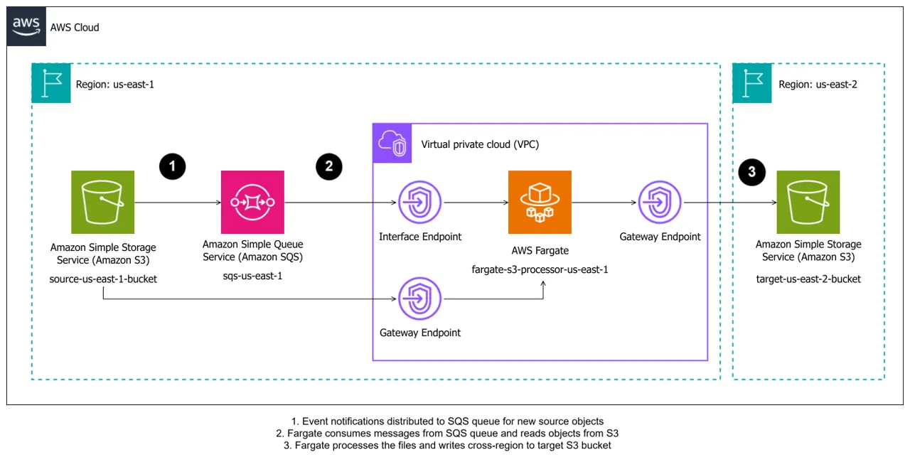
Notice the logical groupings of resources into AWS Cloud, AWS Region and VPC. You don’t necessarily need to include all of these groupings, just the ones that make sense and give extra clarity for your diagram. If all of your workflows take place in a single region, adding the region grouping is superfluous and actually adds clutter. The same arguments can be applied for both the AWS Cloud and VPC groupings - only add them if they’re relevant.
Next to call out is, er, the Call Outs. These are the number labels at various points that correspond to descriptions at the bottom. I’m of the opinion that these should be used when you have long descriptions for a given step, but that it’s perfectly fine to add text within an arrow if it adds clarity.
Using the above resources, you can create diagrams that align with AWS best practices. Just be aware, however, that the point is to make diagrams easy to read. Break rules where you need to!
Other Logical Architectures
While cloud service architectures will suffice for most workflows, there are other logical architectures that might be useful to your organisation. For example:
- Network Architecture - a focus on the VPCs, subnets and other network components that are involved in your workflow, specifying CIDR block ranges and other network properties
- Data Flow Architecture - a focus on how data flow through and are treated by each service in the workflow. For example: are PII treated differently to non-sensitive data? Are some datasets deposited into different buckets for specific reasons?
- Encryption Flows - a focus on how data are encrypted at rest and in transit between services. For example: if you use AWS KMS to encrypt a bucket; whether you use TLS 2.0 or TLS 3.0 for your in-transit data
There are many lenses you can apply at the logical layer to yield different architectures. In all cases, just make sure your diagrams are easy to follow, accurate and provide just the right amount of information, and everyone will thank you for it.
References
None today!